


Letter from Charles Bage to William Strutt ,1803/08/29
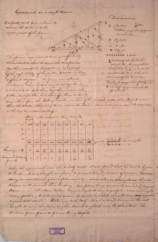
Experiment on a single Frame
Dimensions
A 7 Inches deep
The bottom projection _ square on each side
B 5 5/8 wide
C 5 degrees
H 5/8 degrees
DEFGIKLM 4 Wide
Section of all the limbs except A, the projection being 2 Inches by _, placed all on one side to suit the convenience of the Founder. Thickness every where from 6/8 and 7/8
O a fixed point from whence to measure the distance to the upper point of the frame.
P This left as open as possible for a road
The former experiment having sufficiently demonstrated that to screw the two frames together would be hazardous on account of the possibility of the pillar and walls sinking different degrees. The frame was altered as above. When the two are placed together it is intended to bolt them together as near the pillar as possible, but not suffer them to touch anywhere from the bolt upwards, so that if the middle pillar should sink more than the walls, they may have room to close. Some contrivance must be adopted at the top to prevent reeling.
| Short | ||||||||||
| Weight | The additions long weights | |||||||||
| 1 | 15Gs | 25 | 35 | 45 | 55 | 65 | 75 | 85 | 95 | |
| 2 | – | – | – | – | – | – | – | – | – | |
| 3 | – | – | – | – | – | – | – | – | – | |
| 4 | – | – | – | – | – | – | – | – | – | |
| 60 | 100 | 140 | 180 | 220 | 260 | 300 | 340 | 380 | ||
equal to of E q A short weight 20”2”3”12 short weight
Binding at N 0 1/32 2/32 2/32 3/32 3/32 4/32 5/32 6/32
Increased distance from O 0 0 0 0 1/60 1/40 1/20
When the experiment was about half made, it was found that the nail C began to bend. It was thought necessary to prevent this by means of a prop; because doing so would not give a false security, since when in their places the side Razors will prevent their bending, one frame being previously secured by diagonal bracesÄ The above Casting happening to be very imperfect, I did not weight it any farther; but have no reason to doubt but that it would have supported a great deal more. Reckoning Arch, Roof, Snow or Wind I suppose the real weight it may sometime or other have to support may be 10 or 11 tons, the distance from frame to frame being 10 feet.
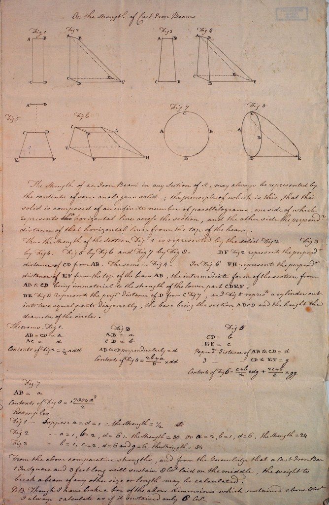
On the strength of Cast Iron Beams
The Strength of an Iron Beam in any section of it, may always be represented by the contents of some analagous solid; the principle of which is this, that the solid is composed of an infinite number of parallelograms, one side of which represents a horizontal line across the section, and the other side the perpendicular distance that horizontal line from the top of the beam.
Thus the strength of the section Fig: 1 is represented by the solid Fig 2. Fig 3 by Fig 4. Fig 5 by Fig 6 and Fig 7 by Fig 8. DF Fig 2 represents the perpendicular distance of CD from AB. The same in Fig 4. _ In Fig 6 FH represents the perpendicular distance of EF from the top of the beam AB, the intermediate form of the section from AB to CD being immaterial to the strength of the lower part CDEF.
DE Fig 8 represents the perpendicular distance of D from C Fig 7; and Fig 8 represents a cylinder cut into two equal parts diagonally, the base being the section ABCD and the height the diameter of the circle.
Theorems.
Fig 1.
AB=CD=a
AC=d
Contents of Fig 2 = _ add
Fig 2
AB=a
CD=b
AB to CD perpendicularly=d
Contents of Fig 4=(26+a)/6 x dd
Fig 5
CD=b
EF=c
Perpendicular distance of AB to CD = d
– – – CD to EF = g
Contents of Fig 6= (c+b)/2 x dg + (2c+b)/6 x gg
Fig 7
AB = a
Contents of Fig 8 =ê 7854a_ / 2
Examples
Fig 1 _ suppose a=d=1 .«. the strength = _
Fig 2 _ – a=1, b=2, d=6 .«. the strength = 30 or a=2, b=1, d=6, the strength =24
Fig 3 _ – b=1, c=2, d=6 and g=6 the strength = 84
From the above comparative strengths, and from the knowledge that a Cast Iron Bar 1 Inch Square and 3 feet long will sustain 8 Cwt laid on the middle, the weight to break a beam of any other size or length may be calculated.
NB. Though I have broke a bar of the above dimensions which sustained about 8 Cut I always calculate as if it sustained only 6 Cwt.
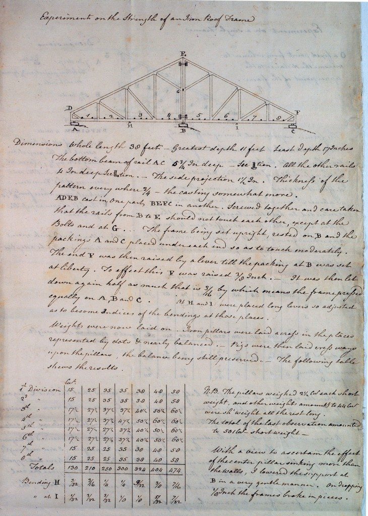
Experiment on the Strength of an Iron Roof Frame
Dimensions whole length 38 feet _ Greatest depth 11 feet least depth 17 Inches. The bottom beam of rail AC 5_ Inches deep _ Section. All the other rails 4 Inch deep Section. _ The side projection 1_ Inches. Thickness of the pattern every where _ – the casting somewhat more.
ADEB cast on one part BEFC in another. Screwed together and care taken that the rails from B to E should not touch each other, except at the Bolts and at GÄ The frame being set upright, rested on B and the packings A and C placed under each and so as to touch moderately. The end F was then raised by a lever till the packing at B was set at liberty. To effect this F was raised 3/8 Inch. _ It was then let down again half as much that is 3/16 by which means the frame pressed equally on A,B and C. At H and I were placed long levers so adjusted as to become Indices of the bendings at those places.
Weights were now laid on. Iron pillars were laid across in the places represented by dots and nearly balanced. _ Pigs were then laid cross ways upon the pillars, the balance being still preserved.. _ The following table shows the results.
Cwt
1st Division 15 25 35 35 38 48 58
2nd – 15 25 35 35 38 48 58
3rd – 17_ 27_ 37_ 37_ 40_ 50_ 60_
4th – 17_ 27_ 37_ 47_ 50_ 60_ 60_
5th – 17_ 27_ 27_ 37_ 40_ 50_ 60_
6th – 17_ 27_ 27_ 37_ 40_ 50_ 60_
7th – 15 25 25 35 38 48 58
8th – 15 25 25 35 38 48 58
Totals 130 210 250 300 324 404 474
Binding H 3/32 3/16 _ _ 9/32 3/8 7/16
– at I 1/32 3/32 3/32 1/8 1/8 5/32 7/32
N.B. The pillars weighed 2_ Cwt each short weight, and other weights amounts to 44 Cwt were short weight all the rest long.
The total of the last observation amounted to 501 Cwt _ short-weight _
With a view to ascertain the effect of the center pillar sinking more than the walls, I lowered the support at B in a very gentle manner. On dropping 1/8 Inch the frames broke in pieces.
Dear Sir
My conscience has long upbraided me for having so long delayed to send you some theorems for ascertaining the strength of cast iron beams. But the care of building two mills, the ordinary business of the present Mill, and what is now become a matter of moment, attention to Military Marches and counter marches, I really find but little leisure.
I have added some experiments on Roof Frames, which have cost no little time or money, but which on our plan were essentially necessary to be ascertained. If these or any thing else in my power to furnish can be either useful or agreeable to you, I shall be much gratified.
Our Mill hands have volunteered so that if ordered off the Works must stop _ have you managed matters more wisely? _ I hope you are perfectly free from all new family afflictions, and remain with respectful complements to Mrs Shutt Dear Sir your obliged Servant
Charles Bage
Shrewsbury
August 29 1803